How To Use A Multimeter is a skill that every electronics enthusiast and professional should master. At HOW.EDU.VN, we provide expert guidance to help you confidently use this essential tool for circuit analysis and troubleshooting. Learn about voltage measurement, current measurement, resistance measurement, and continuity testing with expert advice.
1. Introduction to Multimeters
A digital multimeter (DMM) is an indispensable tool for anyone working with electronics. It’s a versatile device that allows you to diagnose circuits, understand electronic designs, and test various components. The term “multimeter” comes from its ability to perform multiple measurements. A multimeter is essential for measuring voltage, current, and resistance. These measurements are critical for troubleshooting and ensuring the correct operation of electronic circuits.
1.1. Why Use a Multimeter?
A multimeter is your first line of defense when troubleshooting any electronic system. Whether you’re a hobbyist or a professional, a multimeter can help you quickly identify problems and ensure that your circuits are functioning correctly. For instance, you can use a multimeter to verify if a switch is working, check the voltage of a battery, or diagnose a malfunctioning circuit.
The versatility of a multimeter makes it an essential tool in any electronics toolkit. It can measure various parameters like voltage, current, resistance, and continuity, providing a comprehensive overview of the circuit’s health. Knowing how to effectively use a multimeter can save time and prevent costly mistakes by quickly identifying the root cause of issues.
1.2. What Can You Measure with a Multimeter?
The primary measurements you can perform with a multimeter include:
- Voltage: Measures the potential difference between two points in a circuit.
- Current: Measures the flow of electrical charge through a circuit.
- Resistance: Measures the opposition to current flow in a circuit.
- Continuity: Checks for a complete electrical path between two points.
These measurements are essential for diagnosing issues in electronic circuits and ensuring components are functioning correctly. By mastering these basic measurements, you can troubleshoot and maintain electronic systems efficiently. If you are facing challenges in understanding these concepts, consider consulting with the Ph.D. experts at HOW.EDU.VN for personalized guidance.
2. Essential Concepts Before You Start
Before diving into the practical aspects of using a multimeter, it’s crucial to understand some fundamental concepts. These include voltage, current, resistance, and continuity. Grasping these concepts will enhance your ability to interpret multimeter readings and diagnose circuit issues effectively.
2.1. Understanding Voltage
Voltage, often described as electrical potential difference, is the force that drives electrons through a circuit. It is measured in volts (V) and can be either direct current (DC) or alternating current (AC).
- DC Voltage: Flows in one direction and is commonly used in battery-powered devices and electronic circuits.
- AC Voltage: Periodically reverses direction and is typically found in household outlets.
Measuring voltage is crucial for ensuring that components receive the correct power supply and for identifying voltage drops or spikes that can cause malfunctions.
2.2. Understanding Current
Current is the rate at which electric charge flows through a circuit, measured in amperes (A). It indicates the amount of electricity flowing and is essential for determining power consumption and load distribution.
- High Current: Indicates a large flow of charge, potentially causing overheating or damage.
- Low Current: Indicates a small flow of charge, which might lead to insufficient power for components.
Measuring current helps in optimizing circuit performance and preventing overloads that can damage components.
2.3. Understanding Resistance
Resistance is the opposition to the flow of electric current, measured in ohms (Ω). It is a critical factor in determining how much current flows through a circuit for a given voltage.
- High Resistance: Limits current flow, protecting sensitive components.
- Low Resistance: Allows more current to flow, potentially causing damage if not controlled.
Measuring resistance helps in verifying the integrity of resistors and identifying shorts or open circuits.
2.4. Understanding Continuity
Continuity testing checks whether an electrical path exists between two points in a circuit. It is used to ensure that connections are properly made and that there are no breaks in the circuit.
- Continuous Path: Indicates a complete circuit with no breaks.
- Discontinuous Path: Indicates an open circuit or a break in the connection.
Continuity testing is essential for troubleshooting wiring issues, verifying switch functionality, and ensuring that connections are secure.
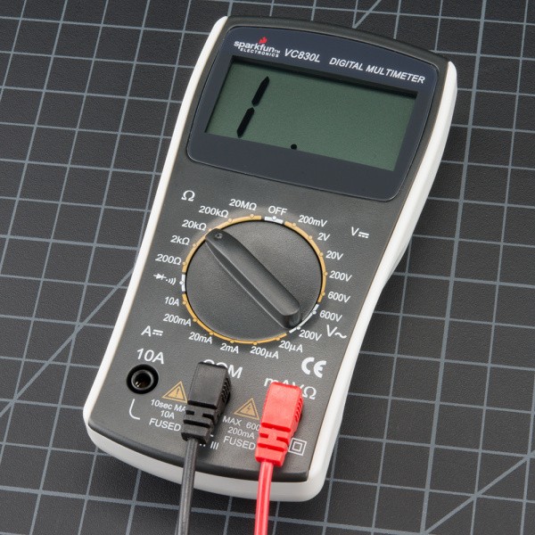
3. Identifying the Parts of a Multimeter
A multimeter typically consists of three main parts: the display, the selection knob, and the ports. Each part plays a crucial role in taking accurate measurements. Understanding these components is essential for effectively using a multimeter.
3.1. The Display
The display usually features four digits and a negative sign. Some advanced multimeters come with illuminated displays, making them easier to read in low-light conditions. The display shows the measured value, units, and any error messages.
- Digital Readout: Provides precise numerical values.
- Backlight: Enhances visibility in dimly lit environments.
- Error Indicators: Alerts the user to out-of-range measurements or other issues.
3.2. The Selection Knob
The selection knob allows you to choose what the multimeter will measure, such as milliamps (mA) for current, volts (V) for voltage, and ohms (Ω) for resistance. The knob also selects the measurement range.
- Voltage Settings: DC and AC voltage measurements.
- Current Settings: Measures current in amperes or milliamperes.
- Resistance Settings: Measures resistance in ohms.
- Continuity Setting: Checks for continuity in a circuit.
3.3. The Ports
The ports are where you plug in the probes. The “COM” port is the common ground, usually connected to the negative (-) side of a circuit. The “10A” port is used for measuring large currents (greater than 200mA), and the “mAVΩ” port is used for measuring current (up to 200mA), voltage, and resistance.
- COM Port: The common or ground port.
- 10A Port: For measuring high currents.
- mAVΩ Port: For measuring voltage, resistance, and low currents.
4. Types of Multimeter Probes
Different types of probes are available for multimeters, each designed for specific applications. Some common types include:
- Standard Probes: Basic probes for general use.
- IC Hook Cables: Cables with hooks for attaching to integrated circuit (IC) pins.
- Alligator Clips: Cables with alligator clips for secure connections.
- Needle-Tipped Probes: Probes with fine tips for precise measurements.
- Tweezers: Probes with tweezers for testing surface-mount components.
4.1. Selecting the Right Probe
Choosing the right probe depends on the specific task. For general use, standard probes are sufficient. For measuring small components on a circuit board, needle-tipped probes or tweezers are more suitable. Alligator clips are useful for making secure, hands-free connections.
4.2. Maintaining Your Probes
Proper maintenance ensures accurate and reliable measurements. Regularly check the probe leads for any signs of damage, such as frayed wires or broken insulation. Replace damaged probes immediately to avoid inaccurate readings or electrical hazards.
5. How to Measure Voltage with a Multimeter
Measuring voltage is one of the most common uses for a multimeter. Here’s how to do it correctly:
5.1. Setting Up the Multimeter for Voltage Measurement
- Plug in the Probes: Connect the black probe to the “COM” port and the red probe to the “VΩmA” port.
- Select the Voltage Type: Turn the selection knob to the appropriate voltage setting. Use “V” with a straight line for DC voltage and “V” with a wavy line for AC voltage.
- Choose the Range: Select the appropriate voltage range. If you are unsure of the voltage level, start with the highest range to avoid overloading the meter.
5.2. Measuring DC Voltage
To measure DC voltage, follow these steps:
- Connect the Probes: Place the black probe on the ground (negative) side of the circuit and the red probe on the voltage (positive) side.
- Read the Display: Observe the voltage reading on the multimeter display.
5.3. Measuring AC Voltage
To measure AC voltage, follow these steps:
- Connect the Probes: Place the probes across the AC source. Polarity does not matter for AC voltage measurements.
- Read the Display: Observe the voltage reading on the multimeter display.
Testing a AA Battery with Multimeter.
5.4. Practical Examples
- Testing a Battery: To test a AA battery, set the multimeter to the 2V DC range. Place the black probe on the negative terminal and the red probe on the positive terminal. A fresh battery should read around 1.5V.
- Measuring a Power Supply: To measure the output of a power supply, set the multimeter to the appropriate DC voltage range (e.g., 20V). Place the black probe on the ground and the red probe on the positive output. The display should show the output voltage, such as 5V or 12V.
5.5. Avoiding Common Mistakes
- Overloading the Meter: If the voltage exceeds the selected range, the meter will display “OL” or “1”. Increase the range setting until a valid reading is obtained.
- Incorrect Polarity: When measuring DC voltage, ensure the probes are connected with the correct polarity. Reversing the probes will result in a negative reading, but it will not damage the meter.
6. How to Measure Resistance with a Multimeter
Measuring resistance is another essential function of a multimeter. This allows you to verify the value of resistors and check for shorts or open circuits.
6.1. Setting Up the Multimeter for Resistance Measurement
- Plug in the Probes: Connect the black probe to the “COM” port and the red probe to the “VΩmA” port.
- Select the Resistance Setting: Turn the selection knob to the resistance (Ω) setting.
- Choose the Range: Select the appropriate resistance range. If you are unsure of the resistance value, start with the highest range to avoid overloading the meter.
6.2. Measuring Resistance
- Isolate the Resistor: Ensure the resistor is not part of an active circuit. Remove it from the circuit if necessary.
- Connect the Probes: Place the probes on either end of the resistor.
- Read the Display: Observe the resistance reading on the multimeter display.
6.3. Practical Examples
- Verifying Resistor Value: To verify the value of a resistor, set the multimeter to a range that is higher than the expected value. For example, to measure a 1kΩ resistor, set the multimeter to the 2kΩ range. The display should show a value close to 1000 ohms.
- Checking for Shorts: To check for a short circuit, measure the resistance between two points that should not be connected. A reading of 0 ohms indicates a short circuit.
6.4. Tips for Accurate Resistance Measurements
- Remove Power: Always disconnect the power supply before measuring resistance in a circuit.
- Avoid Parallel Paths: Ensure that the resistor is not connected in parallel with other components, as this can affect the accuracy of the measurement.
7. How to Measure Current with a Multimeter
Measuring current is slightly more complex than measuring voltage or resistance because it requires you to insert the multimeter in series with the circuit.
7.1. Setting Up the Multimeter for Current Measurement
- Plug in the Probes: Connect the black probe to the “COM” port. For currents up to 200mA, connect the red probe to the “VΩmA” port. For higher currents (up to 10A), connect the red probe to the “10A” port.
- Select the Current Setting: Turn the selection knob to the appropriate current setting. Use “A” with a straight line for DC current and “A” with a wavy line for AC current.
- Choose the Range: Select the appropriate current range. If you are unsure of the current level, start with the highest range to avoid overloading the meter.
7.2. Measuring Current
- Break the Circuit: Disconnect the circuit at the point where you want to measure the current.
- Connect the Multimeter in Series: Connect the red probe to the point where you disconnected the positive side of the circuit, and connect the black probe to the point where you disconnected the negative side of the circuit. This inserts the multimeter in series with the circuit.
- Apply Power: Turn on the power supply.
- Read the Display: Observe the current reading on the multimeter display.
7.3. Practical Examples
- Measuring LED Current: To measure the current flowing through an LED, break the circuit between the power supply and the LED. Connect the multimeter in series with the LED and the power supply. The display should show the current flowing through the LED, typically a few milliamperes.
- Measuring Circuit Current: To measure the total current consumption of a circuit, break the circuit between the power supply and the rest of the components. Connect the multimeter in series with the power supply and the circuit. The display should show the total current being drawn by the circuit.
7.4. Safety Precautions
- Use the Correct Port: Always use the “10A” port for measuring currents above 200mA to avoid blowing the fuse.
- Start with the Highest Range: Begin with the highest current range to avoid overloading the meter.
- Avoid Shorts: Ensure that you do not create a short circuit when inserting the multimeter in series with the circuit.
8. How to Test Continuity with a Multimeter
Continuity testing is used to check whether an electrical path exists between two points. It is useful for troubleshooting wiring issues and verifying switch functionality.
8.1. Setting Up the Multimeter for Continuity Testing
- Plug in the Probes: Connect the black probe to the “COM” port and the red probe to the “VΩmA” port.
- Select the Continuity Setting: Turn the selection knob to the continuity setting. This setting is usually indicated by a diode symbol or a speaker symbol.
8.2. Testing for Continuity
- De-energize the Circuit: Ensure that the circuit is powered off before testing for continuity.
- Connect the Probes: Place the probes on the two points you want to test.
- Listen for the Tone: If there is a continuous electrical path between the two points, the multimeter will emit a tone. If there is no continuity, the multimeter will not emit a tone.
8.3. Practical Examples
- Checking a Wire: To check if a wire is intact, place the probes on either end of the wire. If the multimeter emits a tone, the wire is intact.
- Testing a Switch: To test if a switch is working, place the probes on the switch terminals. When the switch is closed, the multimeter should emit a tone. When the switch is open, the multimeter should not emit a tone.
Multimeter is set to continuity mode.
8.4. Troubleshooting with Continuity Testing
Continuity testing can be used to troubleshoot a variety of issues, such as:
- Broken Wires: If a wire is not conducting electricity, it may be broken or damaged.
- Loose Connections: If a connection is not secure, it may not be providing a reliable electrical path.
- Short Circuits: If two points that should not be connected are showing continuity, there may be a short circuit.
9. Replacing the Fuse in a Multimeter
One of the most common issues with multimeters is blowing the fuse, which typically happens when measuring current incorrectly. Here’s how to replace it:
9.1. Identifying a Blown Fuse
If the multimeter reads “0.00” when measuring current or does not provide any reading, the fuse may be blown. Before you start, it is essential to disconnect the multimeter from any power source and remove the probes.
9.2. Opening the Multimeter
- Remove the Battery Plate: Use a screwdriver to remove the battery plate on the back of the multimeter.
- Remove the Screws: Remove the screws holding the multimeter together.
- Separate the Case: Carefully separate the two halves of the multimeter case.
9.3. Locating and Replacing the Fuse
- Locate the Fuse: Identify the fuse, which is usually a small glass or ceramic cylinder with metal caps on each end.
- Remove the Blown Fuse: Gently pry the blown fuse out of its holder.
- Replace the Fuse: Insert a new fuse of the same type and rating into the holder. Ensure the new fuse is properly seated.
9.4. Reassembling the Multimeter
- Reassemble the Case: Carefully align the two halves of the multimeter case and snap them together.
- Replace the Screws: Reinstall the screws to secure the case.
- Replace the Battery Plate: Reinstall the battery plate and secure it with the screws.
9.5. Importance of Using the Correct Fuse
- Correct Rating: Ensure that you replace the blown fuse with one that has the same current and voltage ratings. Using a fuse with a higher rating can damage the multimeter or create a safety hazard.
- Type of Fuse: Use the correct type of fuse (e.g., fast-blow or slow-blow) as specified by the multimeter manufacturer.
10. Choosing the Right Multimeter
Selecting the right multimeter depends on your specific needs and budget. Here are some factors to consider:
10.1. Key Features to Look For
- Continuity Testing: Essential for troubleshooting wiring issues.
- Auto-Ranging: Automatically selects the appropriate measurement range.
- Backlit Display: Enhances visibility in low-light conditions.
- Accuracy: Ensures precise and reliable measurements.
- Durability: Withstands regular use and potential drops.
- Safety Ratings: Complies with safety standards to protect against electrical hazards.
10.2. Types of Multimeters
- Digital Multimeters (DMMs): Provide precise digital readouts and are suitable for a wide range of applications.
- Analog Multimeters: Use a needle to indicate measurements and are often preferred for observing dynamic changes in a circuit.
- Clamp Multimeters: Measure current without breaking the circuit, using a clamp to sense the magnetic field around a wire.
10.3. Multimeter Recommendations
- For Beginners: A basic digital multimeter with continuity testing and auto-ranging is a good starting point.
- For Professionals: A high-accuracy multimeter with advanced features such as data logging and temperature measurement is recommended.
- For Field Use: A rugged, portable multimeter with a long battery life is ideal for on-site troubleshooting.
If you need assistance in selecting the right multimeter or understanding its specifications, the experts at HOW.EDU.VN can provide personalized recommendations based on your specific requirements.
11. Tips and Best Practices
To ensure accurate and safe multimeter measurements, follow these tips and best practices:
11.1. Safety First
- Disconnect Power: Always disconnect power from the circuit before taking measurements.
- Use Insulated Probes: Use probes with intact insulation to prevent electrical shock.
- Avoid Wet Environments: Do not use a multimeter in wet or damp environments.
- Wear Safety Glasses: Protect your eyes from potential sparks or debris.
- Inspect Leads: Regularly inspect probe leads for damage and replace them as needed.
11.2. Ensuring Accurate Readings
- Calibrate the Multimeter: Periodically calibrate the multimeter to ensure accurate readings.
- Use the Correct Range: Select the appropriate measurement range to avoid overloading the meter.
- Zero the Meter: Before taking measurements, zero the meter to compensate for lead resistance.
- Stable Connections: Ensure that the probes make stable and secure connections with the circuit.
- Avoid Stray Fields: Keep the multimeter away from strong electromagnetic fields that can affect accuracy.
11.3. Troubleshooting Common Issues
- No Reading: Check the battery and fuse to ensure they are functioning correctly.
- Inaccurate Readings: Verify that the multimeter is calibrated and that the correct measurement range is selected.
- Overload: If the multimeter displays “OL” or “1,” increase the measurement range.
- Erratic Readings: Check for loose connections, damaged probes, or interference from nearby devices.
12. Advanced Multimeter Techniques
Once you have mastered the basics, you can explore more advanced techniques to enhance your troubleshooting skills:
12.1. Measuring Diode Forward Voltage
A diode allows current to flow in only one direction. Measuring the forward voltage drop across a diode can help determine if it is functioning correctly.
- Set the Multimeter: Turn the selection knob to the diode test setting (usually indicated by a diode symbol).
- Connect the Probes: Place the red probe on the anode (positive side) of the diode and the black probe on the cathode (negative side).
- Read the Display: The multimeter should display the forward voltage drop, typically between 0.5V and 0.7V for silicon diodes.
If the multimeter displays “OL” or “1,” the diode is either open or connected in reverse. A reading of 0V indicates a shorted diode.
12.2. Testing Transistors
Transistors are semiconductor devices used to amplify or switch electronic signals and electrical power. A multimeter can be used to perform basic tests to determine if a transistor is functioning.
- Identify the Terminals: Determine the base, collector, and emitter terminals of the transistor.
- Set the Multimeter: Turn the selection knob to the diode test setting.
- Test the Base-Emitter Junction: Place the red probe on the base and the black probe on the emitter. The multimeter should display a forward voltage drop.
- Test the Base-Collector Junction: Place the red probe on the base and the black probe on the collector. The multimeter should display a forward voltage drop.
- Reverse Bias Test: Reverse the probes for both junctions. The multimeter should display “OL” or “1,” indicating no conduction.
These tests can help identify common transistor faults such as open junctions, shorted junctions, or reversed polarity.
12.3. Measuring Capacitance
Capacitance is the ability of a component to store electrical energy. Some advanced multimeters can measure capacitance directly.
- Set the Multimeter: Turn the selection knob to the capacitance (F) setting.
- Discharge the Capacitor: Before measuring, discharge the capacitor by shorting its terminals with a resistor.
- Connect the Probes: Place the probes on the capacitor terminals.
- Read the Display: The multimeter should display the capacitance value in farads (F), microfarads (µF), or picofarads (pF).
12.4. Measuring Frequency
Frequency is the number of cycles per second of an AC signal. Some advanced multimeters can measure frequency directly.
- Set the Multimeter: Turn the selection knob to the frequency (Hz) setting.
- Connect the Probes: Place the probes across the AC signal source.
- Read the Display: The multimeter should display the frequency in hertz (Hz).
13. Real-World Applications and Case Studies
Understanding how to use a multimeter can be applied to various real-world scenarios, from simple home repairs to complex industrial applications. Here are a few examples:
13.1. Automotive Diagnostics
- Battery Testing: Use a multimeter to check the voltage of a car battery. A fully charged battery should read around 12.6V.
- Alternator Testing: Measure the voltage output of the alternator while the engine is running. It should be between 13.5V and 14.5V.
- Fuse Testing: Check for continuity across fuses to identify blown fuses.
13.2. Home Appliance Repair
- Power Cord Testing: Check for continuity in power cords to identify breaks or shorts.
- Component Testing: Test the resistance of heating elements in appliances like toasters and ovens to ensure they are functioning correctly.
- Outlet Testing: Measure the voltage at electrical outlets to ensure they are providing the correct voltage (120V in North America).
13.3. Industrial Equipment Maintenance
- Motor Testing: Measure the resistance of motor windings to identify shorts or open circuits.
- Sensor Testing: Check the output voltage or current of sensors to ensure they are within specified ranges.
- Control Circuit Troubleshooting: Use continuity testing to trace wiring issues in control circuits.
By applying multimeter techniques to these scenarios, technicians and engineers can quickly diagnose and repair electrical and electronic issues, saving time and reducing downtime.
14. Continuous Learning and Skill Improvement
The field of electronics is constantly evolving, so it is important to continue learning and improving your multimeter skills.
14.1. Online Resources and Tutorials
- Websites and Forums: Explore online resources such as electronics forums, blogs, and manufacturer websites for tutorials and troubleshooting tips.
- Video Tutorials: Watch video tutorials on platforms like YouTube for visual demonstrations of multimeter techniques.
- Online Courses: Enroll in online courses on platforms like Coursera and Udemy to deepen your knowledge of electronics and multimeter applications.
14.2. Hands-On Practice
- Practice Circuits: Build simple circuits on breadboards to practice measuring voltage, current, and resistance.
- Troubleshooting Exercises: Create simulated faults in circuits to practice troubleshooting techniques.
- Real-World Projects: Work on real-world projects that require you to use a multimeter, such as repairing appliances or building electronic devices.
14.3. Consulting with Experts
- Professional Mentors: Seek guidance from experienced professionals in the field of electronics.
- Online Communities: Participate in online communities and forums to ask questions and share knowledge.
- Expert Consultations: Consider consulting with experts at HOW.EDU.VN for personalized advice and troubleshooting assistance.
By continuously learning and practicing, you can enhance your multimeter skills and stay up-to-date with the latest techniques and technologies.
15. Seeking Expert Assistance at HOW.EDU.VN
While this guide provides a comprehensive overview of how to use a multimeter, complex troubleshooting scenarios may require expert assistance. At HOW.EDU.VN, we offer personalized consultations with Ph.D. experts who can provide in-depth guidance and support.
15.1. Benefits of Consulting with Our Experts
- Personalized Advice: Receive customized advice tailored to your specific troubleshooting needs.
- In-Depth Analysis: Get assistance with complex circuit analysis and diagnostics.
- Real-Time Support: Access real-time support to address urgent issues and questions.
- Skill Enhancement: Improve your multimeter skills and knowledge through expert guidance.
- Peace of Mind: Gain confidence in your troubleshooting abilities with the support of experienced professionals.
15.2. How to Get in Touch
If you are facing challenges in using a multimeter or need expert assistance with a specific project, please contact us at HOW.EDU.VN. You can reach us through the following channels:
- Address: 456 Expertise Plaza, Consult City, CA 90210, United States
- WhatsApp: +1 (310) 555-1212
- Website: HOW.EDU.VN
Our team of Ph.D. experts is ready to provide the support and guidance you need to excel in your electronics endeavors.
16. FAQs About Using a Multimeter
1. What is a multimeter used for?
A multimeter is used to measure voltage, current, resistance, and continuity in electrical circuits.
2. How do I measure voltage with a multimeter?
Connect the black probe to the COM port and the red probe to the VΩmA port. Set the multimeter to the appropriate voltage setting (DC or AC) and range. Place the probes on the two points you want to measure.
3. How do I measure current with a multimeter?
Connect the black probe to the COM port and the red probe to the A port (for current). Break the circuit and connect the multimeter in series with the circuit. Set the multimeter to the appropriate current setting (DC or AC) and range.
4. How do I measure resistance with a multimeter?
Connect the black probe to the COM port and the red probe to the VΩmA port. Set the multimeter to the resistance (Ω) setting and range. Place the probes on the two ends of the resistor you want to measure.
5. How do I test continuity with a multimeter?
Connect the black probe to the COM port and the red probe to the VΩmA port. Set the multimeter to the continuity setting (usually indicated by a diode or speaker symbol). Place the probes on the two points you want to test. If there is continuity, the multimeter will emit a tone.
6. What does “OL” or “1” mean on the multimeter display?
“OL” or “1” indicates that the multimeter is overloaded, meaning the value you are trying to measure is higher than the selected range. Increase the range setting until a valid reading is obtained.
7. How do I replace the fuse in a multimeter?
Disconnect the multimeter from any power source and remove the probes. Open the multimeter case, locate the blown fuse, and replace it with a new fuse of the same type and rating.
8. What is the difference between DC and AC voltage?
DC voltage flows in one direction, while AC voltage periodically reverses direction. DC is used in battery-powered devices, while AC is used in household outlets.
9. What is auto-ranging on a multimeter?
Auto-ranging automatically selects the appropriate measurement range for the value you are trying to measure.
10. How do I choose the right multimeter?
Consider the key features you need, such as continuity testing, auto-ranging, and accuracy. Choose a multimeter that fits your budget and intended use, whether for beginners, professionals, or field use.
Navigating the complexities of electronics can be challenging, but with the right tools and knowledge, you can confidently troubleshoot and repair a wide range of issues. At how.edu.vn, our mission is to empower you with the expertise and support you need to succeed. Contact us today and discover how our Ph.D. experts can help you unlock your full potential in the world of electronics.